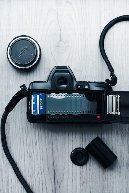
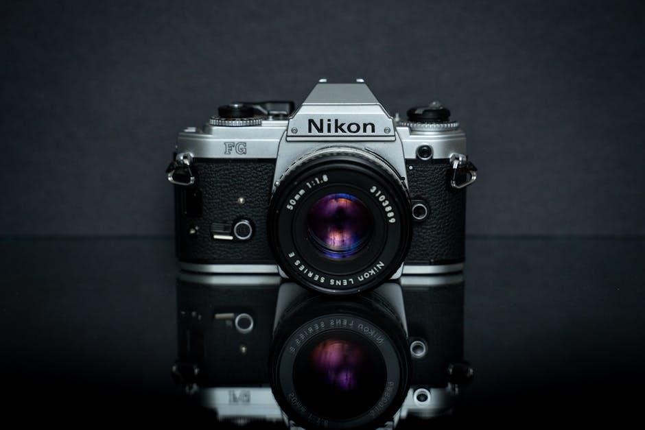
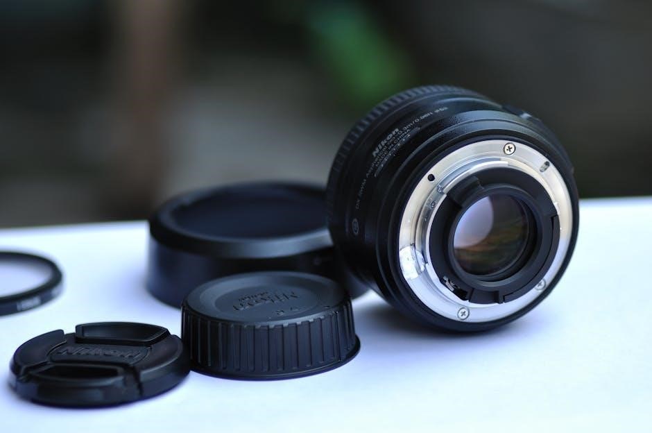
nikon fm2 manual

Overview of the Nikon FM2

The Nikon FM2 is a high-performance 35mm SLR featuring a maximum shutter speed of 1/4000sec, flash synchronization up to 1/250, manual controls, and durable construction․ It offers an advanced metering system and compatibility with various Nikkor lenses, making it a versatile tool for photographers․

The Nikon FM2 is a high-performance 35mm SLR camera designed for both amateur and professional photographers․ Known for its durability and intuitive manual controls, it features advanced capabilities such as a maximum shutter speed of 1/4000sec and flash synchronization up to 1/250․ Its compact design, combined with compatibility with a wide range of Nikkor lenses, makes it a versatile and reliable tool for capturing high-quality images․

1․2 Key Features of the Nikon FM2

The Nikon FM2 boasts a robust design with manual controls, offering precise handling․ It features advanced components like the Type K2 focusing screen and compatibility with AI and non-AI Nikkor lenses․ The camera’s metering system includes automatic maximum aperture indexing, while its shutter speeds range from 1/4000sec to bulb mode, ensuring flexibility for diverse photography needs and lighting conditions․

Key Features of the Nikon FM2

The Nikon FM2 features a maximum shutter speed of 1/4000sec, flash synchronization up to 1/250, manual controls, and a durable, weather-sealed construction for professional-grade photography․

2․1 Maximum Shutter Speed of 1/4000sec

The Nikon FM2 boasts an impressive maximum shutter speed of 1/4000sec, enabling photographers to freeze fast-moving subjects and shoot in bright lighting conditions without overexposure․ This feature, combined with precise aperture control, ensures exceptional image quality and versatility for various shooting scenarios, making it a standout choice for professionals and enthusiasts alike․

2․2 Flash Synchronization Speeds Up to 1/250

The Nikon FM2 supports flash synchronization speeds up to 1/250, allowing photographers to capture well-lit, sharp images in low-light conditions․ This feature enhances creativity by enabling the use of external flash units for balanced exposures, making it ideal for indoor and outdoor photography where additional lighting is required to achieve professional results․

2․3 Manual Controls and Durable Construction

The Nikon FM2 features robust manual controls, offering precise adjustments for aperture, shutter speed, and focus․ Its durable construction ensures long-lasting performance, with a focus on reliability and user-friendly design․ The camera’s build quality and intuitive controls make it a reliable choice for photographers seeking creative freedom and durability in various shooting environments․

Focusing Screens and Accessories

The Nikon FM2 includes a standard Type K2 focusing screen and offers optional Type B2 screens for enhanced focusing accuracy․ Various accessories are available to expand functionality․

3․1 Standard Type K2 Focusing Screen

The Nikon FM2 features the Type K2 focusing screen as a standard accessory, providing a clear and sharp viewfinder image․ This screen is designed for general photography, offering a matte/Fresnel surface with a central focusing spot for precise manual focusing․ It ensures accurate focusing control, making it ideal for various shooting conditions and lens types․

3․2 Optional Focusing Screens (Type B2)

For enhanced focusing precision, the Nikon FM2 offers optional Type B2 focusing screens․ These screens feature a matte/Fresnel surface with a central focusing spot, designed to assist in challenging lighting conditions․ They are interchangeable with the standard Type K2, providing photographers with flexibility based on their specific needs and shooting styles․

Metering System and Exposure Control

The Nikon FM2 features a sophisticated metering system with automatic maximum aperture indexing, ensuring accurate exposure․ Manual controls allow for precise adjustments, offering photographers full creative command․

4․1 Meter Coupling System and Automatic Maximum Aperture Indexing

The Nikon FM2 incorporates a meter coupling system with automatic maximum aperture indexing, enhancing exposure accuracy․ This feature ensures seamless communication between the camera and AI-compatible lenses, automatically adjusting settings for optimal results․ It simplifies the photography process, allowing for precise control over lighting conditions without manual adjustments, thus improving overall image quality effectively․

4․2 Exposure Compensation and Manual Settings

The Nikon FM2 offers exposure compensation of ±2 EV, allowing precise control over lighting conditions․ Manual settings provide full creative freedom, enabling photographers to adjust aperture, shutter speed, and flash synchronization․ This flexibility makes the FM2 ideal for both amateur and professional photographers seeking precise control over their images in various lighting scenarios․

Compatible Lenses and Accessories

The Nikon FM2 supports AI and non-AI Nikkor lenses, offering versatility for photographers․ Additional accessories like focusing screens and camera straps enhance functionality, catering to diverse needs․

5․1 AI and Non-AI Nikkor Lenses Compatibility

The Nikon FM2 is compatible with both AI and non-AI Nikkor lenses, providing photographers with a wide range of optical options․ While AI lenses offer advanced metering capabilities, the camera also supports older non-AI lenses, ensuring backward compatibility․ This versatility allows users to utilize their existing lens collection effectively, enhancing their creative photography experiences with a variety of focal lengths and aperture settings available at their fingertips, making the FM2 a flexible choice for both amateur and professional photographers alike․

5․2 Additional Accessories for Enhanced Photography

The Nikon FM2 supports various accessories to enhance photography experiences․ These include optional focusing screens like the Type B2, which offers a matte/Fresnel surface with a focusing spot for precise control․ Additional accessories such as camera straps, lens hoods, and filters are available to protect and expand the camera’s functionality․ Repair manuals and maintenance resources are also accessible for troubleshooting and long-term care, ensuring optimal performance and durability for photographers of all levels․

Maintenance and Troubleshooting

Regular cleaning of the focusing screens and ensuring moisture-free storage are essential for maintaining the Nikon FM2’s performance․ Common issues like inaccurate metering or shutter malfunctions can often be resolved with basic troubleshooting steps outlined in the manual, ensuring optimal functionality and longevity․

6․1 Cleaning and Care Tips for the Nikon FM2

Regularly clean the Nikon FM2’s focusing screens with a soft, dry cloth to prevent dust buildup․ Ensure the camera is stored in a dry, cool environment to avoid moisture damage․ Use a high-quality cleaning solution for the lens and mirror, and handle the camera with care to maintain its durability and performance over time․

6․2 Common Issues and Solutions

Common issues with the Nikon FM2 include shutter curtain wear and light meter inaccuracies․ Replace worn curtains promptly to prevent exposure errors․ For metering problems, recalibrate or consult a professional․ Regular maintenance and inspection ensure optimal performance and longevity of the camera, maintaining its reliability for photographers relying on its manual controls and precise mechanics․

The Nikon FM2 User Manual

The Nikon FM2 manual provides essential guidance, covering camera operations, features, and troubleshooting․ Available as a PDF, it’s a comprehensive resource for optimal camera use and maintenance․

7․1 Structure and Key Sections of the Manual

The Nikon FM2 manual is structured to guide users through camera operations, focusing on key sections like nomenclature, aperture/focusing index, and shooting modes․ It includes detailed explanations of features such as meter coupling, exposure compensation, and focusing screens, ensuring comprehensive understanding for photographers of all skill levels to maximize camera functionality effectively․

7․2 Downloading and Accessing the Manual

The Nikon FM2 manual is readily available for download as a PDF file, offering 78 pages of detailed instructions․ Users can access it for free from official sources, with options to view online or download for offline use․ The manual is also available on websites like www․orphancameras․com, ensuring easy access for photographers seeking comprehensive guidance on camera operations and features․

Historical Context and Legacy

The Nikon FM2, introduced in the early 1980s, became a landmark camera in Nikon’s history, praised for its reliability and advanced features, earning it a loyal following among photographers․

8․1 Evolution of the Nikon FM Series

The Nikon FM series debuted in the early 1980s, with the FM2 emerging as a refined successor․ It built on the legacy of the original FM, incorporating improved metering systems, faster shutter speeds, and enhanced durability․ The FM2’s popularity soared, leading to variants like the FM2n and FM2/T, solidifying its place as a cornerstone in Nikon’s film camera lineage․

8․2 Popularity Among Amateur and Professional Photographers

The Nikon FM2 gained widespread acclaim for its durability, precise manual controls, and versatility․ Both amateur and professional photographers favored it for its reliability and intuitive design․ Its robust build and advanced features made it a go-to choice for various photography needs, cementing its reputation as a timeless tool in the world of film photography․

Special Models and Variants

The Nikon FM2 series includes notable variants like the FM2n and FM2/T․ These models offer enhanced features, durability, and unique design elements, appealing to enthusiasts and collectors․

9․1 Nikon FM2n (Titanium or Aluminum Shutter)

The Nikon FM2n is an advanced variant of the FM2, featuring a titanium or aluminum shutter for enhanced durability․ It retains the original’s robust design while offering improved materials for longevity, making it a preferred choice for professional photographers seeking reliability and superior performance in demanding conditions․ This model exemplifies Nikon’s commitment to quality and innovation․

9․2 Nikon FM2/T (Titanium Model)

The Nikon FM2/T is a special titanium-bodied version, offering exceptional durability and lightweight construction․ This model combines the FM2’s renowned features with a premium titanium exterior, enhancing both style and functionality․ It appeals to enthusiasts and professionals seeking a high-performance camera with a unique aesthetic, while maintaining the reliability and excellence of the FM2 series․

Camera Specifications

The Nikon FM2 features a 35mm film format, titanium or aluminum shutter, and weighs approximately 540g․ It measures 142mm x 90mm x 60mm, ensuring portability and durability․

10․1 Technical Details and Performance

The Nikon FM2 boasts a maximum shutter speed of 1/4000sec, flash synchronization up to 1/250, and manual controls․ It features a durable construction, a meter coupling system, and compatibility with AI and non-AI Nikkor lenses, ensuring precise exposure control and versatility for photographers seeking high performance in a compact design․

10․2 Dimensions and Weight

The Nikon FM2 measures 142mm in width, 90mm in height, and 60mm in depth, weighing approximately 540 grams․ Its compact and lightweight design, combined with a durable aluminum alloy body, makes it easy to carry while maintaining robust construction, ensuring both portability and reliability for photographers on the go․

User Reviews and Ratings

The Nikon FM2 manual has an average rating of 8․2 from 3 users, praised for its clear structure and detailed instructions, covering 78 pages and applicable to various models․

11․1 Average Rating and User Feedback

The Nikon FM2 manual holds an average rating of 8․2 from users, with praise for its clear structure and detailed instructions․ Photographers appreciate its 78-page depth, covering camera operations, metering, and lens compatibility․ Many highlight its applicability to various models like the FM2n and FM2/T, making it a valuable resource for both amateur and professional photographers seeking precise control over their craft․

11․2 Comparison with Other Models

The Nikon FM2 is often compared to models like the FM and FE, with its 1/4000sec shutter speed and 1/250 flash sync standing out․ While similar in design, the FM2’s meter coupling lever isn’t retractable, limiting compatibility with non-AI lenses․ Despite this, its compact size and advanced features make it a favorite among photographers, balancing portability with professional-grade performance․

Resources and References

Official Nikon FM2 manuals are available online as PDFs, offering detailed instructions and specifications․ Websites like orphancameras․com provide additional resources and historical insights for photographers․

12․1 Official Nikon FM2 Manual Sources

The official Nikon FM2 manual is available for free download from Nikon’s website and trusted sources like ManualsLib․ It covers camera operation, features, and troubleshooting, ensuring comprehensive guidance for users․ Additionally, the manual is compatible with variants like the FM2n and FM2/T, making it a versatile resource for photographers of all levels․

12․2 Online Communities and Forums

Online forums like Flickr, Reddit, and photography communities offer extensive discussions and resources for Nikon FM2 users․ These platforms provide troubleshooting tips, user experiences, and insights into maximizing the camera’s potential․ Enthusiasts and professionals share knowledge, creating a vibrant community for learning and improvement․ Websites like ManualsLib and orphan cameras also host valuable resources for FM2 enthusiasts․

Continue Reading

arctic cat atv repair manual free download

Arctic Cat ATV repair manuals provide comprehensive guides for servicing and maintaining various models, offering detailed instructions, wiring diagrams, and troubleshooting tips for optimal performance and repair․

Overview of Arctic Cat ATV Models and Manuals

Arctic Cat ATVs span various models, including 2005-2010, 2011-2015, and 2016-present, each requiring specific repair manuals․ These manuals cover maintenance, troubleshooting, and detailed repair procedures, featuring high-quality diagrams, wiring schematics, and step-by-step instructions․ They are designed for both novice and experienced users, ensuring accurate and efficient repairs․ Manuals are tailored to individual models, such as the 250, 300, 400, and 700 series, providing precise guidance for optimal performance and longevity of the vehicle․

Importance of Using Official Repair Manuals

Official Arctic Cat repair manuals are essential for accurate and safe ATV repairs․ They provide precise instructions, wiring diagrams, and specifications, reducing errors․ These manuals ensure compliance with manufacturer standards, maintaining warranty validity and vehicle performance․ They cover diagnostics, maintenance, and complex repairs, making them indispensable for both professionals and DIY enthusiasts․ Using official manuals prevents costly mistakes and ensures reliability, making them a vital resource for any ATV owner seeking to perform repairs effectively and efficiently․

Where to Download Arctic Cat ATV Repair Manuals for Free

Arctic Cat ATV repair manuals are available for free download from official resources and third-party websites, offering comprehensive guides for various models and years․

Official Arctic Cat Resources and Websites

Arctic Cat provides official resources through their website, including service manuals, parts catalogs, and wiring diagrams for various ATV models․ These materials are designed to help users maintain and repair their vehicles efficiently․ By accessing the official portal, users can download detailed guides specific to their model year and type, ensuring accuracy and reliability․ This resource is invaluable for both DIY enthusiasts and professional mechanics seeking authentic information․

Third-Party Websites Offering Free Downloads

Several third-party websites offer free downloads of Arctic Cat ATV repair manuals, providing accessible resources for users․ These platforms often include comprehensive manuals, wiring diagrams, and troubleshooting guides for various models․ While these sources can be convenient, users should verify the authenticity and completeness of the documents to ensure they are suitable for their specific needs․ These sites are particularly useful for those seeking immediate access without subscription or purchase requirements․

Arctic Cat Forums and Communities for Manual Sharing

Arctic Cat forums and online communities are valuable resources for sharing repair manuals and troubleshooting tips; Many enthusiasts and mechanics post free downloadable manuals, covering various models and years․ These forums often include discussions on common issues, DIY repairs, and maintenance advice; Users can also request specific manuals or guidance, fostering a collaborative environment․ Popular forums include Arctic Cat’s official community and third-party sites dedicated to ATV repairs, making them excellent platforms for accessing and sharing repair resources․

How to Use the Repair Manual Effectively

Understand the manual’s structure, use the index for quick navigation, and refer to diagrams for visual guidance․ Apply instructions systematically for successful repairs and maintenance․

Navigating the Manual: Table of Contents and Index

The repair manual begins with a detailed table of contents, organizing sections by major components and procedures․ The index provides an alphabetical listing of topics, enabling quick access to specific repairs․ Users can locate information efficiently by referencing these tools․ The manual is also searchable, allowing keyword searches for precise instructions․ Familiarizing yourself with these navigation aids ensures you can quickly find the information needed for repairs․ This structure is designed to streamline the repair process, making it user-friendly even for complex tasks․

Understanding Diagrams, Wiring Schematics, and Instructions

The manual includes high-quality diagrams and wiring schematics, providing clear visual guidance for repairs․ Each diagram is paired with detailed instructions, explaining each step of the process․ Wiring schematics are color-coded and annotated to simplify troubleshooting electrical systems․ Instructions are written in a straightforward manner, ensuring clarity for both novice and experienced users․ These visual and textual aids work together to help users understand complex procedures, making even the most challenging repairs manageable with precision and confidence․

Applying the Manual to Common Repairs and Maintenance

The manual provides detailed procedures for common repairs, such as replacing belts, servicing brakes, and addressing electrical issues․ It includes troubleshooting guides to diagnose problems efficiently․ Maintenance tasks, like oil changes and tire pressure adjustments, are clearly outlined with torque specifications and step-by-step instructions․ By following the manual, users can perform routine checks and repairs, ensuring their Arctic Cat ATV runs smoothly and reliably․ This resource empowers owners to handle both minor and major servicing with confidence and precision․

Troubleshooting Common Issues in Arctic Cat ATVs

Arctic Cat ATVs may experience issues like faulty ignition, weak acceleration, or electrical malfunctions․ Diagnosing these problems requires consulting repair manuals for precise solutions and fixes․

Identifying Fault Codes and Diagnostic Procedures

Arctic Cat ATV repair manuals include detailed fault code lists and diagnostic steps to help identify and resolve issues․ By referencing these codes, users can pinpoint problems such as ignition faults or sensor malfunctions․ Manuals provide step-by-step procedures for testing components like fuel systems, electrical circuits, and engine performance․ This structured approach ensures accurate diagnoses, enabling effective repairs․ Coverage spans various models, ensuring compatibility and comprehensive troubleshooting guidance for common and model-specific issues․

Common Problems and Solutions for Specific Models

Arctic Cat ATV models often experience issues like faulty fuel systems, electrical component failures, and cooling system leaks․ For 2010 models, common problems include malfunctioning fuel injectors and faulty ignition switches․ The 2012 models frequently encounter issues with the cooling system and throttle sensor․ Older models, such as the 2005-2007 series, may have transmission and belt wear issues․ Solutions typically involve replacing damaged parts, cleaning or recalibrating sensors, and ensuring proper fluid levels․ Manuals provide detailed repair steps for these model-specific challenges, ensuring effective resolutions․

DIY Repair Tips and Tools

Essential tools for Arctic Cat ATV repair include wrenches, screwdrivers, and multimeters․ DIY tips emphasize proper workspace setup, referencing manuals, and ensuring safety during maintenance and fixes․

Essential Tools for ATV Repair and Maintenance

Essential tools for Arctic Cat ATV repair include wrenches, screwdrivers, pliers, and a multimeter․ A torque wrench ensures proper bolt tightening․ Jack stands and ramps are crucial for lifting․ Air compressors and tire pressure gauges help with tire maintenance․ Specialized tools like spark testers and brake bleed kits are also necessary․ Always refer to the repair manual for specific tool requirements․ Organizing tools in a structured workspace enhances efficiency and safety during repairs and regular maintenance tasks․

Step-by-Step Guidance for Beginner-Friendly Repairs

Beginners can start with basic maintenance tasks like oil changes and air filter cleaning․ Always refer to the repair manual for clear instructions․ Start with small repairs, such as replacing spark plugs or checking tire pressure․ Use the manual’s diagrams to identify components․ Practice safety by disconnecting the battery before starting work․ Troubleshoot common issues like faulty ignition or carburetor problems using the manual’s guidance․ Gradually move to more complex tasks as confidence and skills improve, ensuring each step follows the manual’s advice․

Safety Precautions and Best Practices

Always wear protective gear, ensure the ATV is stable, and disconnect the battery before starting repairs․ Follow manual guidelines to avoid accidents and ensure safe practices․

Safety Guidelines for Working with ATVs

Always disconnect the battery before starting repairs to prevent accidental startups․ Wear protective gear, including gloves and safety glasses․ Ensure the ATV is on a level surface and securely supported with jack stands․ Never work under an unsupported vehicle․ Follow proper lifting techniques to avoid injury․ Keep flammable materials away from the workspace․ Refer to the manual for model-specific safety precautions and adhere to all warnings․ Regularly inspect tools and equipment for damage․ Maintain a clean and well-lit workspace to minimize hazards․

Environmental Considerations for Repairs

Properly dispose of hazardous materials like oil, coolant, and batteries to prevent environmental contamination․ Use eco-friendly cleaning products and minimize water usage during washing․ Recycle metals and plastics from discarded parts․ Avoid draining fluids directly onto the ground․ Store chemicals in sealed containers and follow local regulations for waste disposal․ Refer to the repair manual for guidelines on handling environmentally sensitive components․ Always aim to reduce waste and promote sustainable practices during repairs․

Model-Specific Repair Information

This section provides detailed repair guides for Arctic Cat ATV models, covering diagnostics, maintenance, and part replacements for 2005-2010, 2011-2015, and 2016-present models, ensuring precise fixes․

2005-2010 Arctic Cat ATV Models: Key Repairs

For 2005-2010 Arctic Cat ATV models, common repairs include addressing engine issues, electrical system faults, and suspension wear․ Manuals for these years provide detailed steps for fixing problems like faulty starters, carburetor adjustments, and belt replacements․ Wiring diagrams and torque specifications are included to ensure accurate repairs․ These resources are essential for maintaining optimal performance and extending the lifespan of your ATV, covering models such as the 250, 300, 400, and 700 series․ Regular maintenance and troubleshooting guides are also emphasized to prevent major breakdowns․

2011-2015 Arctic Cat ATV Models: Common Issues

Arctic Cat ATVs from 2011 to 2015 often face issues like faulty fuel injectors, electrical system malfunctions, and cooling system leaks․ Repair manuals for these models provide detailed solutions for problems such as engine stalling, faulty sensors, and transmission slipping․ Models like the 450, 550, and 700 frequently require repairs to their clutches and drive belts․ The manuals also cover routine maintenance tasks to prevent these issues, ensuring optimal performance and reliability for both recreational and utility-focused ATVs during this period․

2016-Present Arctic Cat ATV Models: Modern Repairs

Modern Arctic Cat ATVs from 2016 onwards feature advanced systems, but common issues include ECU software updates, sensor calibrations, and CVT belt replacements․ Repair manuals detail procedures for addressing problems like engine light illuminations, faulty throttle-by-wire systems, and differential leaks․ Models such as the 800, 1000, and ProWler often require precise diagnostics and specialized tools․ These manuals emphasize advanced troubleshooting techniques, ensuring owners can maintain and repair their high-performance ATVs efficiently, leveraging the latest technological advancements in off-road vehicles․

Additional Resources and Support

Arctic Cat offers extensive support through official resources, forums, and third-party websites, providing free manuals, wiring diagrams, and expert advice for ATV repairs and maintenance needs․

Arctic Cat Dealer Support and Service Centers

Arctic Cat dealers provide valuable resources, including official repair manuals, service bulletins, and expert advice․ Visiting a certified service center ensures access to genuine parts and professional diagnostics․ Dealers often offer detailed wiring diagrams, troubleshooting guides, and model-specific repair tips․ Their extensive knowledge covers various ATV models, from older 2005 units to modern 2023 designs․ Whether you’re addressing complex issues or routine maintenance, Arctic Cat dealers are equipped to provide reliable support, ensuring your ATV runs optimally․ Their assistance complements free manual downloads, offering a comprehensive solution for owners․

Online Communities and Forums for Repair Advice

Online forums and communities dedicated to Arctic Cat ATVs are invaluable resources for repair advice․ Platforms like Arctic Cat Forum and ATV Forums host discussions where owners share experiences, solutions, and tips․ Members often provide detailed troubleshooting guides, wiring diagrams, and repair strategies for specific models․ These communities are particularly useful for diagnosing issues and finding cost-effective solutions․ Many users upload free manuals and service guides, making them accessible to everyone․ Engaging with these forums can enhance your repair skills and provide support from experienced enthusiasts and mechanics․

Utilizing Arctic Cat ATV repair manuals ensures effective maintenance and repair, enhancing performance and longevity․ Accessing free downloads from official and trusted sources guarantees accurate guidance for all models and years, empowering owners to tackle repairs confidently and efficiently․

Final Thoughts on Using Repair Manuals Effectively

Effectively using Arctic Cat ATV repair manuals ensures proper maintenance and repair․ These manuals provide detailed instructions, diagrams, and troubleshooting tips, making complex tasks manageable․ They cover essential aspects like wiring, diagnostics, and model-specific issues, helping owners maintain their vehicles efficiently․ Accessing free, high-quality downloads from trusted sources like Arctic Cat’s official platforms or reputable forums ensures accuracy and reliability․ By following the manual’s guidance, users can enhance their ATV’s performance, extend its lifespan, and reduce repair costs․ Regularly referring to these manuals fosters a deeper understanding of the vehicle, empowering owners to handle repairs with confidence and precision․

Continue Reading

honeywell alarm manual

The Honeywell Alarm Manual provides comprehensive guidance for installing, operating, and maintaining your security system. It covers key features like motion sensors, door/window sensors, and Total Connect 2.0 for remote monitoring. Understanding this manual ensures optimal system performance and enhances your security setup effectively.

Overview of Honeywell Alarm Systems

Honeywell Alarm Systems are renowned for their reliability and advanced security features. Designed to integrate seamlessly with smart home devices, these systems offer a user-friendly interface for easy monitoring and control. With a range of sensors and remote monitoring capabilities through platforms like Total Connect 2.0, Honeywell provides comprehensive security solutions for homes and businesses. Their scalability ensures they can adapt to various property sizes and specific security requirements efficiently.

Importance of Reading the Manual

Reading the Honeywell Alarm Manual is essential for understanding system functionality, optimizing security, and avoiding potential errors. It provides detailed instructions for installation, operation, and troubleshooting, ensuring users can fully utilize advanced features like motion sensors and remote monitoring. The manual also highlights safety precautions and maintenance tips, helping users maintain their system’s effectiveness and longevity. By following the guidelines, users can enhance their security setup and respond effectively to alarms, ensuring peace of mind and reliable protection.

Installation and Setup

The Honeywell Alarm System installation is straightforward with its compact design and lightweight components. It includes motion sensors, door/window sensors, and a control panel. Follow the user manual for proper setup to ensure all features function optimally, providing reliable security for your premises.

Step-by-Step Installation Guide

  1. Unpack all components, including the control panel, sensors, and mounting hardware.
  2. Place motion sensors in strategic locations to cover high-traffic areas.
  3. Mount door/window sensors to ensure proper alignment for accurate detection.
  4. Sync sensors with the control panel following the manual’s pairing instructions.
  5. Mount the control panel in a central location for easy access.
  6. Connect the power supply and test all components to ensure functionality.
  7. Refer to the manual for detailed programming and customization options.

Following these steps ensures a secure and efficient setup of your Honeywell Alarm System.

Components and Packaging Content

The Honeywell Alarm System package includes a control panel, motion sensors, door/window sensors, proximity tags, power supplies, and mounting hardware. Additional components like a keypad and user manual are also provided. Ensure all items are included and undamaged before installation. Refer to the manual for a detailed list of contents and compatibility with optional devices like smoke detectors or Z-Wave automation tools.

Key Features of Honeywell Alarm Systems

Honeywell Alarm Systems offer advanced security features, including motion sensors, door/window sensors, and remote control via Total Connect 2.0. They provide real-time monitoring, custom scene creation, and tamper alarms, ensuring comprehensive home protection with user-friendly controls and seamless integration with smart devices for enhanced safety and convenience.

Motion Sensors and Door/Window Sensors

Honeywell motion sensors use K-band microwaves for accurate detection, reducing false alarms. Door/window sensors monitor entry points, triggering alerts when unauthorized access is detected. These devices ensure comprehensive security coverage, integrating seamlessly with the alarm system for reliable protection. Their advanced technology and user-friendly design make them essential components of Honeywell’s security solutions, providing peace of mind and enhanced home safety.

Remote Control and Total Connect 2.0

The Honeywell system offers remote control via keypad or proximity tags for convenient operation. Total Connect 2;0 enables real-time monitoring and control through a web portal or mobile app. This platform allows users to receive alerts, manage automation devices, and create custom scenes for enhanced security and convenience. It ensures seamless integration and remote accessibility, making it a powerful tool for modern security needs.

System Operation and Monitoring

The Honeywell system operates through keypads and proximity tags, displaying alarm conditions and memory of past events. Remote monitoring via Total Connect 2.0 enhances security management.

Understanding Alarm Conditions and Memory

The Honeywell system logs each alarm event, showing the affected zones and the type of alarm on the keypad. This memory feature aids in identifying and resolving issues, ensuring the system functions reliably. Users can review past alarms to understand triggers, whether from fire, intrusion, or other causes, helping maintain security and system integrity effectively.

Using the Keypad and Proximity Tags

The keypad allows users to arm, disarm, and monitor the system, while proximity tags offer a hands-free alternative for quick access. Enter a PIN or present a tag to interact with the system. This streamlined process ensures secure and efficient operation, providing users with a convenient way to manage their security setup effectively.

Troubleshooting and Maintenance

Troubleshooting common issues ensures system reliability; Regularly check sensors, update software, and verify device compatibility to maintain optimal performance and warranty validity.

Common Issues and Solutions

Common issues include false alarms, sensor malfunctions, and connectivity problems. Solutions involve resetting the system, updating software, and ensuring devices are compatible. Regularly test sensors and check for firmware updates to prevent issues. Tamper alarms may require adjusting settings or replacing faulty components. Refer to the manual for specific troubleshooting steps to resolve problems effectively and maintain system reliability.

Software Updates and Warranty Information

Regular software updates ensure your Honeywell system remains secure and functional. Visit the Honeywell website or use Total Connect 2.0 to check for firmware updates. The limited warranty covers defects in materials and workmanship for a specified period. Using unauthorized devices may void the warranty. Refer to the manual for details on updating software and understanding warranty terms to maintain your system’s performance and coverage.

Advanced Security Features

Honeywell Alarm Systems offer advanced security features including tamper alarms, enhanced system security, scene creation for customized responses, and user management for controlled access.

Tamper Alarms and System Security

Tamper alarms trigger when unauthorized interference is detected, ensuring system integrity. In Day mode, internal sounders activate, while full alarms occur in Set mode. The system provides advanced security features, including secure communication and encryption, to prevent unauthorized access. Indicators on the control panel notify users of tamper events, offering an additional layer of protection and monitoring for enhanced system reliability and user confidence.

Scene Creation and User Management

Scene creation allows users to configure specific system settings for different situations, enhancing convenience and security. Through Total Connect 2.0, users can create custom scenes to arm/disarm systems or control devices. User management enables administrators to add, remove, or modify user access, ensuring only authorized individuals can operate the system. This feature provides flexibility and security, allowing tailored system responses for various scenarios and users.

Programming and Customization

Programming mode allows users to customize system settings, such as scene creation and user management. Customization options enable tailored security responses, enhancing system functionality and user experience.

Programming Mode Commands

Programming mode commands allow users to customize system settings. Enter a field number and required data to modify configurations. Commands include bypassing zones, viewing event logs, and adjusting sensor sensitivity. Users can navigate through menus using arrow keys and save changes with the “Save” command. This feature ensures tailored security setups, optimizing system performance for specific needs. Proper use of commands requires careful adherence to manual instructions to avoid errors.

Customizing Alarm Responses and Settings

Customizing alarm responses and settings allows users to tailor their system to specific needs. Users can program unique responses for different alarm triggers, such as motion detection or door/window breaches. Settings can be adjusted via the keypad or remotely through Total Connect 2.0. Customization options include scene creation, user management, and Z-Wave automation integration. These features enhance security and convenience, ensuring the system adapts to individual preferences and lifestyles seamlessly.

Fire Safety and Alarm Systems

Honeywell fire safety systems integrate smoke and heat detectors with audible warnings for early detection and response. They ensure comprehensive protection and quick alerts, enhancing safety protocols effectively.

Automatic Fire Alarm Components

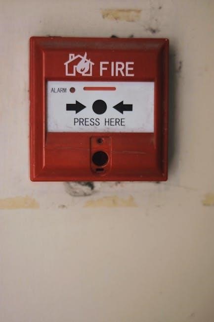
An automatic fire alarm system by Honeywell includes smoke detectors, heat detectors, manual pull stations, and audible warning devices. These components work together to detect potential fires early and alert occupants. Smoke detectors identify particles in the air, while heat detectors sense temperature changes. Manual pull stations allow for manual activation, ensuring quick response. The system is controlled by a central fire alarm panel, which monitors all devices and triggers alarms when necessary.

Heat Detectors and Smoke Detectors

Honeywell systems include heat and smoke detectors to ensure comprehensive fire detection. Smoke detectors identify smoke particles in the air, while heat detectors detect abnormal temperature increases. Both types are essential for early fire detection. Smoke detectors are available in optical or ionization designs, while heat detectors can be fixed-temperature or rate-of-rise models. Together, they provide reliable fire safety, ensuring timely alerts and enhancing overall system efficiency and reliability.

Mastery of your Honeywell alarm system comes with thorough manual review. Follow final tips for optimal performance and refer to provided resources for further assistance and troubleshooting.

Final Tips for Effective System Use

Regularly check sensors and ensure all devices are powered and connected. Update software via Total Connect 2.0 for enhanced features. Replace batteries promptly and test sensors monthly. Train all users on basic operations and emergency procedures. Secure access with strong PINs or proximity tags. Review alarm history to identify patterns and improve security. Schedule annual professional maintenance for optimal performance and reliability.

Resources for Further Assistance

Visit Honeywell’s official website for detailed user manuals, guides, and FAQs. Access the Total Connect 2.0 portal for remote system management and updates. Download specific manuals like the Lynx Touch L5200 or L5100 for advanced features. Contact Honeywell support directly for personalized assistance. Refer to the provided links for troubleshooting, programming commands, and warranty details to ensure optimal system performance.

Continue Reading

the cine lens manual

The Cine Lens Manual is a comprehensive guide to cinema optics, blending art and science. Written by experts Jay Holben and Christopher Probst, it offers clear, illustrated insights for all filmmakers.

Overview of the Comprehensive Guide

The Cine Lens Manual is a detailed exploration of cinema optics, offering insights into the art, science, and history of cinematographic lenses. Designed for filmmakers of all levels, it covers fundamental concepts, optical principles, and practical applications. With extensive illustrations and clear language, it serves as both an educational resource and a practical reference. The manual bridges technical and creative aspects, making it indispensable for understanding lens design, functionality, and their impact on visual storytelling in modern and historical contexts.

Authors and Their Expertise

Authors Jay Holben and Christopher Probst bring over 60 years of combined experience in cinematography, education, and technical journalism. Holben, a renowned director and producer, and Probst, an ASC member, offer deep insights into cinema optics. Their expertise spans lens design, optical principles, and practical applications, making them trusted authorities in the field. This collaboration ensures the manual is both comprehensive and accessible, catering to professionals and enthusiasts alike.

Key Features of the Manual

The Cine Lens Manual is a detailed resource covering optics, design, and history. It features clear language, extensive illustrations, and practical applications. The manual includes chapters on lens basics, optical concepts, and customization, making it a versatile guide for filmmakers. Its accessible style ensures complex topics are understandable, catering to all skill levels. This comprehensive guide is essential for cinematographers, directors, and anyone seeking a deeper understanding of cinema optics.

Understanding the Basics of Cine Lenses

The Cine Lens Manual introduces fundamental concepts of cinema optics, explaining how lenses function and their role in capturing images. It explores optical principles and their filmmaking applications.

Defining the Lens: Fundamental Concepts

A cine lens is a precision optical instrument designed to capture images for filmmaking. It consists of glass or plastic elements arranged to focus light onto a camera sensor or film. Key concepts include focal length, which determines the angle of view, and aperture, controlling light entry and depth of field. Lenses also feature mechanical components like focus and zoom controls. Understanding these basics is essential for harnessing the lens’s creative potential in storytelling and visual expression, as detailed in The Cine Lens Manual.

Optical Principles and Their Role in Filmmaking

Optical principles form the backbone of cine lens functionality. Refraction and diffraction dictate how light behaves through the lens, influencing image sharpness and clarity. Chromatic aberration control ensures accurate color reproduction, while depth of field management shapes the visual narrative. These principles are crucial for achieving desired aesthetic effects, such as bokeh or selective focus, enabling filmmakers to craft compelling visual stories. The Cine Lens Manual elaborates on these principles, providing a foundation for both technical and creative decision-making in cinematography.

Design and Construction of Cine Lenses

Cine lenses are crafted with precision, blending optical and mechanical excellence. Advanced engineering ensures optimal performance, while customization options empower filmmakers to tailor visuals to their artistic vision.

Optical Designs in Action

Optical designs in cine lenses are a perfect balance of art and science, ensuring exceptional image quality. From anamorphic to spherical designs, each type offers unique visual characteristics. Advanced coatings minimize flares and distortions, while aspherical elements enhance sharpness. Modern designs cater to Ultra HD 8K standards, delivering pristine clarity. Customizable options allow filmmakers to achieve distinct looks, making optical design a critical tool in storytelling. The evolution of optical technology continues to push creative boundaries, providing cinematographers with precise control over their visual narratives.

Mechanical Aspects of Lens Construction

The mechanical construction of cine lenses is meticulously engineered for precision and durability. High-quality materials ensure robustness, while focus and zoom mechanisms provide smooth, accurate control. The design emphasizes ergonomic functionality, with features like interchangeable mounts and modular components. Weather-sealing and precise gear systems enhance reliability in demanding environments. These mechanical aspects are crucial for maintaining optical performance and enabling filmmakers to achieve consistent, high-quality results. Every detail is crafted to support the creative process, ensuring lenses are both tools and extensions of the cinematographer’s vision.

History and Evolution of Cinematographic Lenses

The history of cinematographic lenses traces the evolution from early optical designs to modern innovations, shaped by technological advancements. Jay Holben and Christopher Probst detail this journey in The Cine Lens Manual, exploring how lens developments have influenced filmmaking aesthetics and techniques over the decades.

Historical Development of Lens Technology

The evolution of cinematographic lenses began with early optical designs inspired by photography. Innovations like anamorphic lenses in the 1950s revolutionized widescreen formats. Advances in materials and coatings improved image quality, while modern designs integrate digital metadata. The Cine Lens Manual traces this journey, detailing how lens technology has adapted to filmmaking needs, from silent films to contemporary digital cinema, shaping visual storytelling and artistic expression.

Impact of Lens Innovations on Filmmaking

Lens innovations have profoundly shaped filmmaking, enabling new creative possibilities. Advances in optics and mechanics allowed for improved depth of field control and image quality. Anamorphic lenses introduced unique visual aesthetics, while high-speed lenses enhanced low-light shooting. These developments democratized filmmaking, making advanced techniques accessible to all levels of productions. The Cine Lens Manual explores how such technological leaps have empowered filmmakers to push boundaries, transforming the medium and enriching visual storytelling across genres and generations.

Practical Applications and Customization

The Cine Lens Manual explores how filmmakers apply lenses in modern productions, emphasizing customization to meet creative demands. It highlights versatility and performance in tailoring optics for unique storytelling needs.

Utilizing Lenses in Modern Filmmaking

The Cine Lens Manual dives into the practical applications of cinema lenses in contemporary filmmaking, covering technical and aesthetic considerations. It explores how modern lenses are tailored for 8K resolution, anamorphic shooting, and specialized effects. The guide emphasizes customization options, such as modifying focus throws and coatings, to meet specific creative needs. By bridging the gap between theory and practice, the manual empowers filmmakers to make informed decisions, ensuring lenses are integral to their storytelling process. This section is invaluable for cinematographers, directors, and crew seeking to maximize lens capabilities in modern productions.

Modifying and Customizing Cine Lenses

Modifying and Customizing Cine Lenses explores how filmmakers tailor optics to meet specific creative needs. From adjusting focus throws to swapping lens coatings, these tweaks enhance performance and aesthetics. The manual details optical and mechanical customizations, such as anamorphic lens adapters or vintage-style modifications, to achieve unique visual effects. It also covers practical examples, like optimizing lenses for 8K resolution or specialized lighting conditions, ensuring filmmakers can adapt their tools for diverse storytelling demands. This section highlights the versatility of cine lenses in modern cinematography.

Evaluation and Testing of Cine Lenses

The Cine Lens Manual outlines advanced techniques for testing lenses, ensuring optimal performance in filmmaking. It details methods to evaluate sharpness, contrast, and distortion, providing clear metrics for lens assessment.

Methods for Testing and Qualifying Lenses

The Cine Lens Manual details rigorous testing processes to ensure lens performance. Key methods include evaluating sharpness, contrast, and distortion using resolution charts under controlled conditions. Additional tests assess flare, veiling glare, and chromatic aberration to determine optical integrity. Mechanical inspections verify focus and zoom accuracy, crucial for cine lenses. These systematic approaches ensure lenses meet high standards, providing filmmakers with reliable tools for capturing cinematic excellence.

Understanding Lens Performance Metrics

Performance metrics are crucial for evaluating lens quality. The Cine Lens Manual explains key parameters such as MTF (Modulation Transfer Function) for sharpness, T-stop for light transmission, and distortion percentages. These metrics help cinematographers assess optical precision and consistency. Additionally, the manual covers chromatic aberration, focus breathing, and lens flare, providing a detailed framework to understand and select the right lens for specific creative and technical demands in filmmaking.

Continue Reading

5208 silent knight manual

The Silent Knight 5208 Manual provides essential guidance for installing, operating, and maintaining the SK-5208 Fire Control/Communicator, ensuring compliance with safety standards and optimal system performance.

1.1 Overview of the Silent Knight 5208 Fire Control/Communicator

The Silent Knight 5208 is a 10-zone fire alarm control panel, expandable to 30 zones, designed for reliable fire detection and communication. It features UL 864 listing, intelligent photoelectric smoke sensors, and a digital communicator for robust system performance. Suitable for commercial fire alarm systems, it ensures compliance with NFPA standards, offering advanced functionalities for safety and efficiency. Its modular design allows seamless integration with accessories like the SK-5235 touchpad, providing user-friendly control and monitoring capabilities.

1.2 Importance of the Manual for Installation and Operation

The manual is crucial for proper installation, programming, and operation of the SK-5208; It ensures compliance with fire safety codes like NFPA 72 and provides step-by-step instructions, preventing errors and ensuring system reliability. Technicians rely on it for configuring zones, connecting relays, and troubleshooting. Adhering to the manual’s guidelines guarantees optimal performance, safety, and adherence to industry standards, making it indispensable for installers and operators to maintain a reliable fire alarm system.

Features and Specifications of the SK-5208

The SK-5208 is a 10-zone fire alarm control panel, expandable to 30 zones, featuring UL 864 compliance, intelligent photoelectric smoke sensors, and a reliable digital communicator.

2.1 10-Zone Fire Alarm Control Panel (Expandable up to 30 Zones)

The SK-5208 is a versatile 10-zone fire alarm control panel, designed to support up to 30 zones with the use of SK-5217 Zone Expanders, offering flexibility for various system configurations. This expandability ensures the panel can adapt to growing security needs, making it suitable for both small and large facilities. The system’s modular design allows for seamless integration of additional zones, enhancing scalability without compromising performance or reliability.

2.2 UL 864 Listing and Compliance with NFPA 71 and 72

The SK-5208 is UL 864 listed, ensuring compliance with fire safety standards. It meets NFPA 71 and NFPA 72 requirements, guaranteeing reliable performance in fire alarm systems. This certification ensures the panel operates effectively under fire conditions, providing critical alerts and communication. Compliance with these standards is essential for system reliability and adherence to fire safety codes, making the SK-5208 a trusted solution for fire alarm installations.

2.3 Intelligent Photoelectric Smoke Sensors

The SK-5208 features advanced intelligent photoelectric smoke sensors, designed for accurate fire detection. These sensors minimize false alarms by distinguishing between smoke particles and other environmental factors. With UL 864 listing and compliance with NFPA 71 and 72, they ensure reliable performance in fire alarm systems. Their intelligent technology enhances detection accuracy and system responsiveness, providing a robust solution for fire safety applications.

2.4 Digital Communicator for Reliable Fire Alarm Systems

The SK-5208’s digital communicator ensures seamless and reliable transmission of fire alarm signals to monitoring stations. UL 864 listed, it complies with NFPA 71 and 72 standards, guaranteeing efficient communication in emergencies. This feature enhances system reliability, enabling swift response to alarms. Its advanced technology integrates with the control panel, ensuring accurate and timely signal transmission, which is crucial for fire safety and emergency management systems. This communicator is a vital component of the SK-5208’s comprehensive fire alarm solution.

Installation Requirements and Precautions

Proper grounding and static protection are critical for the SK-5208. Use a wrist strap when handling components to prevent damage. Follow safety guidelines for installation.

3.1 Grounding and Static-Sensitive Components

Proper grounding is essential for the SK-5208 to ensure reliable operation and prevent damage. Static-sensitive components require careful handling. Always use a wrist strap connected to a grounded surface when working with the panel. Avoid touching circuit boards or components without proper grounding to prevent static discharge. Grounding ensures system stability and protects against electrical interference. Failure to ground the system can lead to malfunctions or damage. Follow all safety guidelines for handling static-sensitive devices to maintain optimal performance and longevity of the control panel.

3.2 Mounting the SK-5208 Panel

The SK-5208 panel must be mounted in a central, easily accessible location, ensuring compliance with local fire codes. Use the provided mounting hardware to secure the panel to a sturdy surface. The panel’s weight and size require a stable installation to prevent damage. Mounting in a dry, cool environment is recommended to maintain optimal performance. Follow the manufacturer’s guidelines for installation height and clearance. Refer to the manual for detailed mounting instructions to ensure proper installation and system functionality. Proper mounting is critical for reliable operation and safety.

3.3 Wiring and Connection Guidelines

Proper wiring is critical for the SK-5208 panel’s functionality. Use approved wire gauges and ensure all connections are secure to prevent signal loss.Ground the panel correctly to avoid static damage, as static-sensitive components are present. Follow the manual’s wiring diagram for zone connections, power supply, and communicator setup. Avoid crossing wires to minimize interference. Test all connections post-installation to ensure reliability. Adhere to local electrical codes and manufacturer guidelines for a safe and compliant installation. Proper wiring ensures optimal system performance and reliability.

Programming the SK-5208 Panel

Program the SK-5208 panel to configure zones, set relay contacts, and enable advanced features. Refer to the manual for detailed instructions and examples, ensuring proper system customization.

4.1 Zone Configuration and Expansion Options

The SK-5208 panel supports up to 10 zones out of the box, expandable to 30 zones using the SK-5217 Zone Expander. This flexibility allows customization to suit various facility sizes and fire safety requirements. Zone configuration is detailed in the programming manual, ensuring proper setup for optimal performance. The system also integrates with a digital communicator for reliable alarm monitoring and reporting, meeting UL 864 and NFPA standards for fire alarm systems. Proper configuration ensures seamless operation and compliance with safety regulations.

4.2 Relay Contact Connections (Example: Door Holder Application)

The SK-5208 panel features programmable relay contacts for integrating auxiliary devices. Figure 3-10 in the manual illustrates relay connections for a door holder application, enabling automated door closure during alarms. Proper wiring ensures reliable operation, while the example provides a clear guide for similar setups. This functionality enhances system versatility and ensures compliance with fire safety codes, allowing seamless integration of additional safety mechanisms. Detailed instructions in the manual ensure correct implementation for optimal performance.

4.3 Advanced Programming Features

The manual details advanced programming options for the SK-5208, enabling custom configurations for enhanced fire safety. Features include zone-specific settings, custom alarm responses, and integration with auxiliary systems. Users can program relays for specialized applications and set up unique notification protocols. The SKSS software simplifies advanced programming tasks, allowing for tailored system responses. These features ensure the SK-5208 adapts to complex fire safety needs while maintaining compliance with fire codes and standards, providing a robust and flexible fire alarm solution.

Basic Operating Instructions

The SK-5208 manual provides clear steps for daily operations, including user key functions, touchpad navigation, and alarm acknowledgment procedures, ensuring smooth system management and compliance with fire safety standards.

5.1 User Key Operations

The SK-5208 manual details user key operations, enabling users to perform essential functions without requiring a user code. This includes resetting alarms, silencing notifications, and accessing basic system controls. The user key simplifies daily interactions, ensuring quick responses during emergencies. The control panel’s piezo sounder will continue to alert until all alarms are acknowledged. These operations are designed for ease of use, allowing personnel to manage the system efficiently while maintaining fire safety protocols.

5.2 On-Board Touchpad Functionality

The SK-5208 features an on-board touchpad designed for intuitive system control. Users can navigate through menus, acknowledge alarms, and access system status with ease. The touchpad interface streamlines operations, allowing quick access to critical functions. LED indicators provide visual feedback for user inputs, ensuring clear communication. This functionality enhances user experience, making it simple to interact with the fire control/communicator effectively, even during emergency situations.

5.3 Alarm Acknowledgment and Silencing Procedures

The SK-5208 control panel features a straightforward process for acknowledging and silencing alarms. Once an alarm is triggered, the system alerts users through visual and audible signals. Users can acknowledge alarms using the on-board touchpad or a user key, which temporarily silences the audible alerts. The piezo sounder will automatically silence after all alarms have been acknowledged. Proper alarm acknowledgment ensures timely response and system reset, maintaining fire safety and operational efficiency;

Maintenance and Troubleshooting

This section covers routine maintenance tasks and common troubleshooting steps to ensure the SK-5208 operates efficiently and addresses any issues promptly.

6.1 Routine Maintenance Tasks

Regular maintenance ensures the SK-5208 operates reliably. Ground yourself with a wrist strap to protect static-sensitive components. Clean smoke sensors monthly to prevent false alarms. Check all wiring connections for integrity. Test alarm functions and communication systems periodically. Replace batteries as specified. Inspect relays and contacts for wear. Update software if necessary. Refer to the manual for detailed procedures to maintain optimal performance and compliance with fire safety standards.

6.2 Common Issues and Solutions

Common issues with the SK-5208 include false alarms from dirty smoke sensors, communication failures, and power supply problems. Clean sensors monthly to prevent false alarms. Check wiring connections for integrity and ensure proper grounding. Verify that the digital communicator is functioning correctly. For power issues, ensure the system is receiving the correct voltage and that batteries are charged. Refer to the manual for troubleshooting steps and solutions to maintain compliance with UL 864 and NFPA 72 standards.

6.3 Repair Kits and Replacement Parts

For the SK-5208, Silent Knight offers repair kits like the UDC3000/UDC3300 repair kit (Art. 51-52-33-01E) and replacement parts such as the 5280 Status Display Module. These kits ensure quick fixes for common issues. Always use genuine parts to maintain system integrity and compliance with UL 864. Contact Silent Knight Sales at 800-328-0103 for ordering. Proper installation of replacement parts is critical to avoid system malfunctions and ensure reliability in fire alarm operations. Refer to the manual for part compatibility and installation guidelines.

Compliance and Fire Code Requirements

The SK-5208 complies with UL 864 and NFPA 71, 72 standards. Ensure instructions are displayed next to the panel as per NFPA 72 fire code requirements.

7.1 NFPA 72 Standards for Fire Alarm Systems

NFPA 72 outlines requirements for fire alarm systems, including installation, maintenance, and testing. The SK-5208 complies with these standards, ensuring reliable performance and safety. Proper installation and operation as per NFPA 72 are critical for system effectiveness. Regular inspections and testing must be conducted to maintain compliance and ensure all components function correctly. Adherence to these standards helps protect lives and property by providing a robust fire alarm system.

7.2 Displaying Instructions Next to the Panel

NFPA 72 requires that operating instructions be displayed next to the SK-5208 panel. These instructions must be framed and easily accessible to ensure compliance. They provide critical information for system operation, troubleshooting, and maintenance. Proper display ensures that users can quickly reference procedures during emergencies or routine tasks, promoting safety and efficiency. Legibility and proximity to the panel are essential for adherence to fire safety regulations and optimal system management.

7.3 UL Listings and Certifications

The SK-5208 is UL 864 listed and complies with NFPA 71 and 72 standards, ensuring reliability and safety. UL certification validates the panel’s performance under rigorous testing, meeting industry standards for fire alarm systems. This certification is crucial for system approval and ensures compliance with local fire codes. The UL mark confirms the panel’s adherence to safety and operational requirements, providing assurance to installers, authorities, and end-users of its quality and reliability in critical fire alarm applications.

Additional Resources and Support

Visit Silent Knight’s official website for manuals, downloads, and SKSS software. Contact technical support at 800-328-0103 for assistance. Additional resources include user guides and repair kits.

8.1 Silent Knight Website and Downloads

Visit the official Silent Knight website for comprehensive resources, including the SK-5208 manual, SKSS software, and technical documents. Downloads are available for easy access to installation guides, operational manuals, and programming instructions. Ensure compliance with fire codes by referencing the latest updates and support materials. The website also provides links to troubleshooting guides and repair kits, making it a one-stop solution for all your fire control/communicator needs.

8.2 Technical Support and Sales Contact Information

For assistance with the SK-5208, contact Silent Knight Technical Support at 800-328-0103. Sales inquiries can also be directed to this number. Support is available for troubleshooting, system repairs, and general questions. Visit the Silent Knight website for additional contact options, including email and online forms. The website also provides access to a dedicated support team and resources for resolving common issues. Ensure timely resolution by reaching out to their experienced professionals.

8.3 SKSS Software Availability

The SKSS software is available for download on the Silent Knight website at www.silentknight.com. It is essential for programming and configuring the SK-5208 panel. After downloading, refer to the installation manual (P/N 151240) for guidance. The software enhances system functionality and ensures compliance with fire safety standards. Additional resources and support are also accessible on the Silent Knight website to assist with software installation and operation.

Continue Reading